Introduction
Ubiquiti have a real-world link simulation tool to assist with selecting the correct airFiber or airMax product for your application. It uses geographic coordinates using maps overlaid with line-of-sight and Fresnel zone clearances which account for the earth's curvature, link budget, expected capacity, signal levels, and network coverage.
The following is a guide on how to use Ubiquiti's airLink tool to design and plan Point to Point (PTP) or Point to Multi-Point (PTMP) Wireless Network Links.
Instructions
Open a browser to https://link.ui.com
In the Search box, enter an address for your Point to Point/s wireless network link.
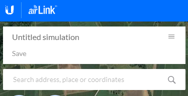
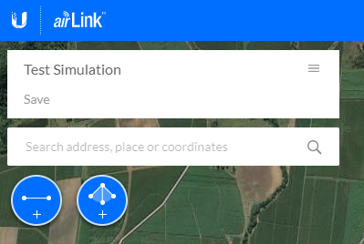
Enter a name for your simulation, and select the Point to Point (PTP), or Point to Multi-Point (PMTP) icon at the top left of the screen.
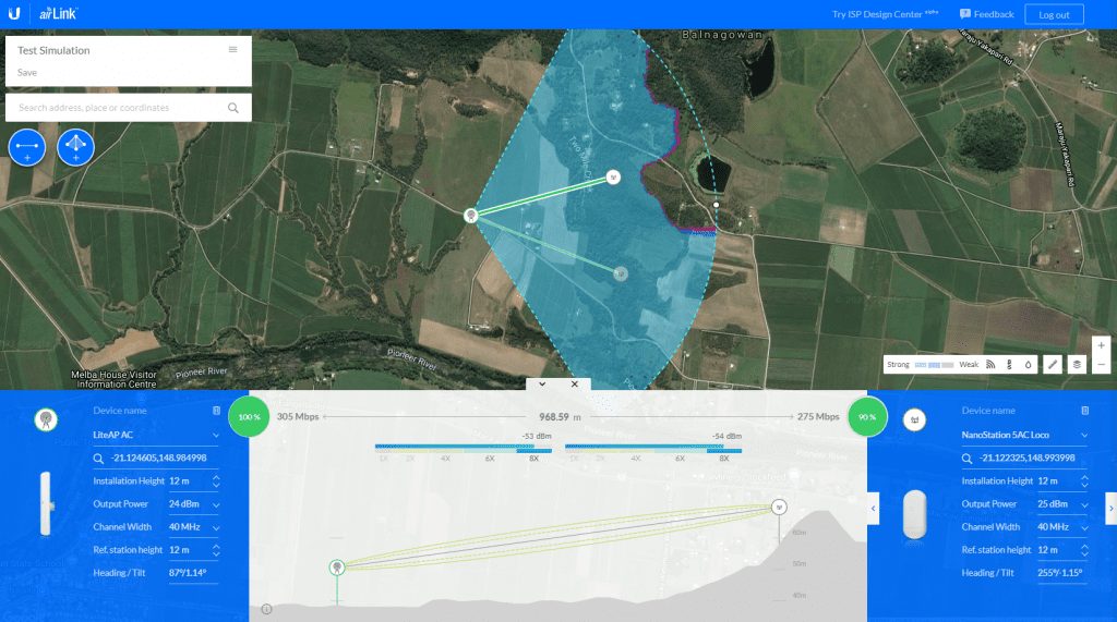
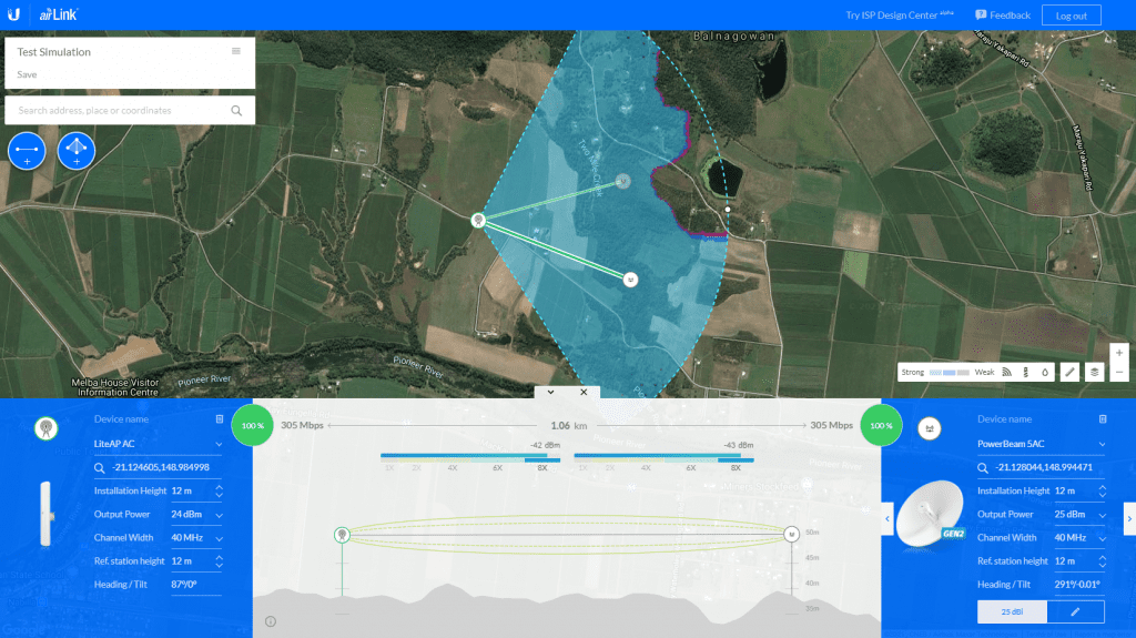
On the map, select and move the client devices to the desired end points. The tool will show a green line for an unobstructed link, and red for an obstructed link.
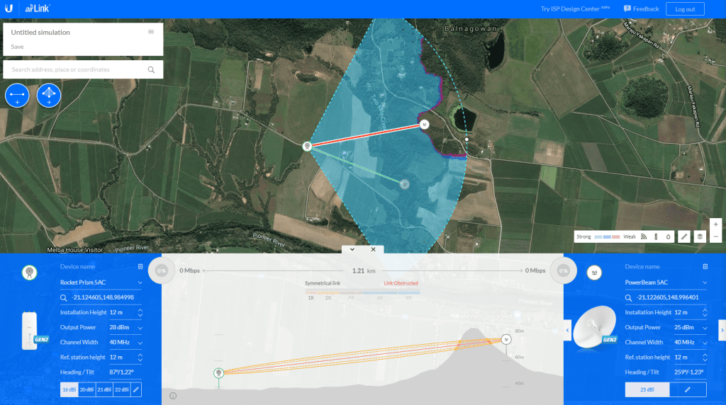
You can select the Device Type from a drop down menu.
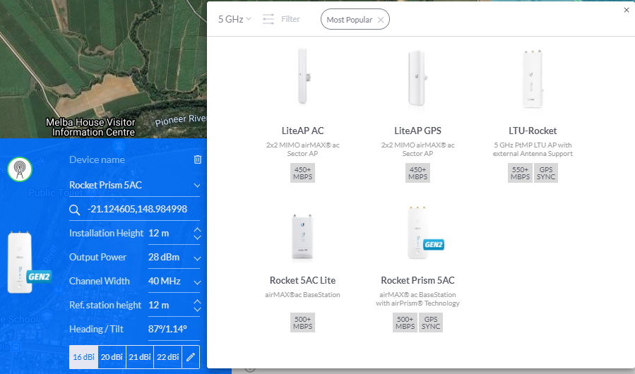
Other options you can choose include the following:
- Installation Height
- Output Power
- Channel Width
- Ref. station height
- Heading / Tilt
Each time you select a different end point device, the Fresnel zones will automatically recalculate, giving a you a good idea of how the system will work for that area.